Autonomous Sumo Robot

FIGURE 1: Messy pairs of wires to/from sumo bot on Arduino Mega.
|
KEYWORDS: C++, Embedded, Sensors, Actuation, prototyping, encoders, controls
I started the Autonomous Sumo Robot about two years ago for the annual RoboGames competition near San Francisco, which is a reboot of the San Francisco Robot fighting that used to be televised. The specific competition is the 3KG sumo competition, where two sumos are put into a meter diameter ring and one robot wins by pushing the other robot out of the ring. I thought it would be a good project to build up practical engineering skills. http://robogames.net/rules/all-sumo.php I already taught Arduino to kids because through a outreach program and I also taught Arduino to two clubs at my community college at the time so I choose Arduino for my processing unit. The rest of the parts for the a high-torque(SLOW), high-grip sumo robot with a vacuum system to suck itself to sumo ring(allowing the sumo to take full advantage of high torque mechanical system. I wanted a high-torque suction sumo because the most documented and known sumos are made for speed. I thought my best chance at doing well in the competition would be one that can counter the faster sumos, and I thought it would be the most interesting to do something different than the common sumos. |
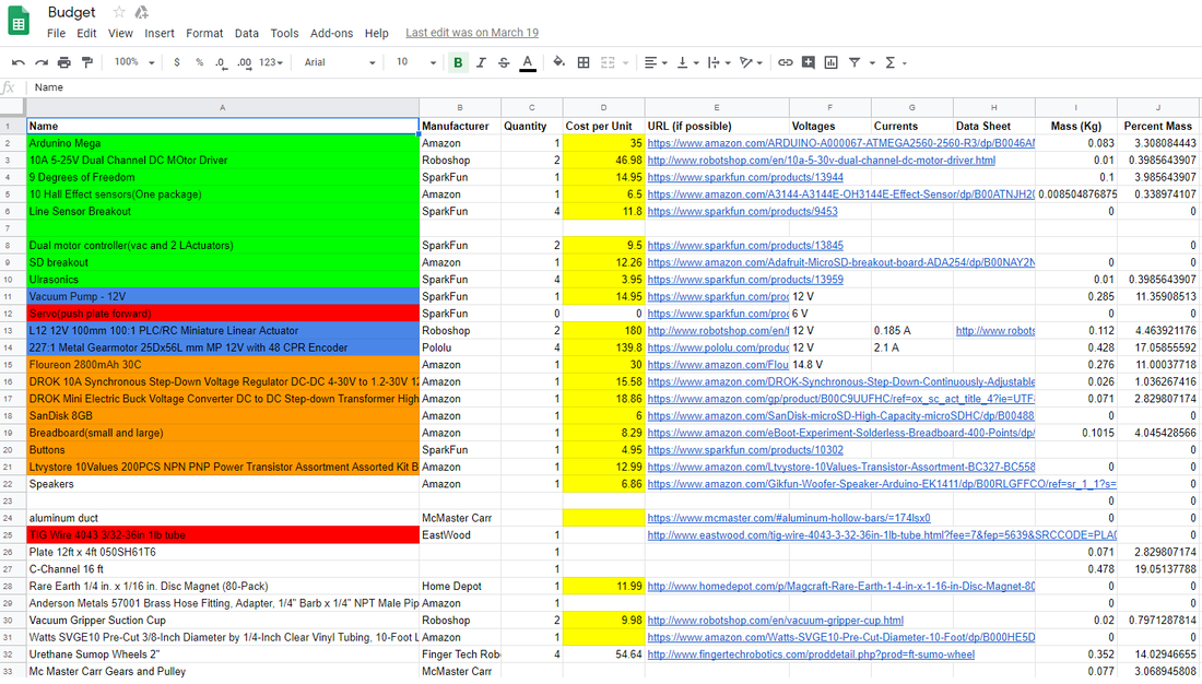
FIGURE 2: List of items to use for the sumo, most have been ordered.
HARDWARE
The hardware of the sumo the Arduino, sensors, power systems, and power drawing mechanical devices. The Arduino is the main processing board, and it uses a language that is almost 100% C++. The Arduino Mega has 16MHz clock speed, 54 Digital and 16 IO pins and 256Kb of flash memory and 8Kb of SRAM. It operates pretty slow and low memory for most microcontrollers and microprocessors available but the robot will be slow to move anyways and I was the most familiar with Arduino when I started so I decided to stick with the Mega, I'll probably switch it out later after I have a full functioning robot.
The sumo has many sensors, so many sensors that the code for the robot is mainly having the robot rotate or go forward based on the combinations of sensor readings. The current robot configuration has 4 ultrasonic distance sensors (two forward, the other two are ~45 degree from the front on both sides). The 4 ultrasonic sensors are used to find the enemy sumo and to direct our sumo to go directly towards the enemy(most of the time). Then there are 4 infared line sensors that will be be in the four corners of the sumos body facing the floor. The infared sensors are for the sumo to tell if they have gone over the edge of the sumo ring(which is a different color than the rest of the ring). When the sumo goes over the line it will try to get back in unless the sumo knows its pushing the enemy sumo out of the ring. Each motor has two encoders, which allows for pretty precise direction and speed control of the sumo as a whole(unless the wheels are slipping).
The power system of the sumo serve to get power from the battery to the Arduino, sensors, actuation devices. The power system starts with the battery, the sumos battery is a 3S LiPo with a charge of 2800 mAh. Then 3 buck converters, one high amperage buck converter to have a constant voltage to motor drivers for the 12 volt motors. Then one buck converter for the 5 volt sensors and Arduino, and other buck converter for the 3.3 volt sensors. Then there are the motor drivers that connect the high amperage buck converter to the motors to control them with the controls from the Arduino, encoders. The main power consuming devices are the high-torque motors, each using a max of 12V and a stall current of 2.1A. Then after getting a working metal body and next version of software, I will add a vacuum system to try to effectively suck the sumo to the ring floor and take advantage of the high torqued motors.
Software
The software for the sumo is very simple but is fairly long(about 1300 lines so far, but a lot of blank lines for easier reading). The software has to filter the readings from all the distance sensors and first determine if its a bad reading, then decide on what actions to do next. If the robot is confident(for a few cycles) that the sumo doesn't see the enemy then it must rotate until it sees the enemy. When the sumo sees the enemy then the sumo starts to move towards the enemy while orienting itself so the sumo is going straight for the enemy. If the far right sensor sees the enemy the sumo has to make a harder right turn to face the enemy. Then it'll keep orienting itself until most front sensors read about the same distance, which means the sumo is going straight towards the enemy sumo. Then if any of the line sensors go off then the sumo has to try to save itself from falling off the ring with various maneuvers based off which line sensor is triggered, unless the sumo knows it is pushing the enemy sumo out of the ring. So most of the code is just dealing with filtering the sensor data, and performing actions based off the data from the sensors. I hope to add PID control later on, but I'm not sure how effective it will be with such slow motors. Here is my most recent copy of my code, it hasn't been fully updated to be optimized and readable but to work and a bunch of sensors on a cardboard box and LEDs. I will make the next draft after I get a metal body done.
| sumo_second_draft.ino |
Progress
Spring 2018
Finished the first and second draft of Arduino code. The second draft deals with the 4 ultrasonic sensors and 4 infrared line sensors. The second draft code works with the the 8 sensors. The motors(As seen in figure 3) are very slow, so there is no speed control on the motors, its either full power clockwise or counter-clockwise. I plan to add to add PID later if I gear the sumo up, since I'm familiar with PID for the class I teach at UC Berkeley. Two mechanical friends joined me on this project, they wanted to build the entire metal body. They designed a drive gear system for the motors, but could't machine the C-channels for the drive gear system. After a few attempts they forgot about the sumo.At this point I have also discovered that the ultrasonics are very slow and so I bought some infrared distance sensors. The ultrasonic distance sensors are slow because they use sound for sensing and if there is nothing close for that sound to bounce off it, the sensors can take longer than a 1/10th of a seconds, which is bad especially for 4 ultrasonic distance sensors. I also don't have of my pictures about testing the sumo sensors my phone from that time became corrupted and I wasn't planning on documenting the process at the time.

FIGURE 3: First platform to mount the motors.
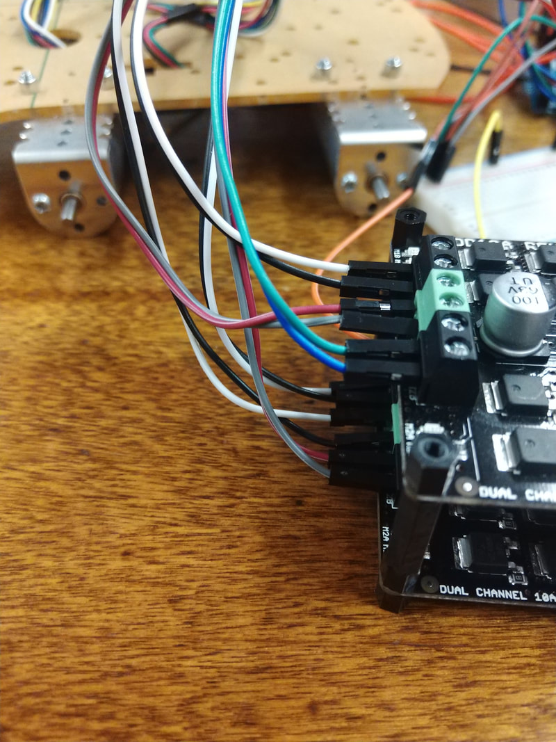
FIGURE 4: Another view of the motors on the first platform, but with a view of the motor drivers.
Spring 2019
I started working on the project again. This time I wanted to start with the mechanical parts for the body of the sumo, to have a semi-permanent platform for mounting the electronics. So I started learning how to machine the C-channel with a drill press and various saws during the weekends I was back from UC Berkeley, using my uncle's tools. I had planned to use the gear system that my mechanical friends made, but the parts seemed very expensive, especially to use for the parts I tried to machine. So instead of using the expensive parts, I did some research online and found out that 3D printers have a lot of cheap pulley systems and parts and I also found some cheap ball bearings meant for RC cars. So I machined some C-channel and bought some 3D printer parts and made two 1:1 "Gear boxes" as seen in figure 5. These drive systems would protect the motors from the stress of placed on the shafts of the wheels. Then being cheap and easy to make, the drive systems will be good for a semi-permanent body to make one working sumo, where I can upgrade each part as needed. At this point I need to connect the two drive systems, but the electronics on a platform, and redo the Arduino code and start on the vacuum system. Now I have to leave for an internship for the summer and have to leave sumo parts.

FIGURE 5: First finished drive system for two wheels(one side) of the sumo, made with minature ball bearings and 3D printer pulley parts.
